
Using Reference Images in Blender
Learn best practices for using reference images in Blender to ensure accurate scale, alignment, and organization in your 3D modeling workflow.
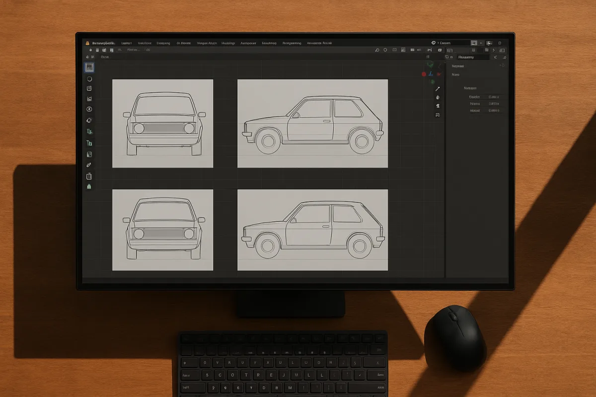
Reference accuracy is a coordinate-system problem
The useful way to think about reference images in Blender is not as drawing guides. They are measurements expressed through an image, and your job is to make each image agree on a single world scale.
I am describing this in Blender 5.0, whose image-format and colour-management documentation is current in the supplied research. The underlying viewport workflow has been stable for several versions, but Blender’s UI labels do move, so confirm details against your installed build.
When a model looks wrong despite careful tracing, the problem is usually not topology. It is that the front image, side image, and model do not share the same assumptions about height, width, depth, or camera projection.
A front blueprint may imply that a vehicle is two metres wide. A side blueprint may have been exported at a slightly different pixel scale. If you trace both without calibration, Blender lets you create a clean mesh around contradictory evidence.
That is why I start with scale calibration, even on a stylised prop. It is not a rigid rule that every game asset needs real-world millimetres, but every asset needs an internally consistent size relationship.
Begin with a known dimension
Set Blender’s scene units before adjusting the reference. In Scene Properties, choose Metric or Imperial, then set the length display that suits the project. This does not magically make imported artwork accurate, it gives your numerical decisions a meaningful unit. [5]
Find one reliable measurement in the reference before modelling. For an appliance, that might be total width. For a chair, seat height. For a character sheet, it could be the stated overall height or a deliberately chosen unit such as head height.
Import the image through Blender’s Add menu, then Image, then Reference. A Reference image enters the 3D scene as an editable image plane, whereas Background images are associated with particular views. That distinction matters when you need to position, organize, and compare several drawings. [1]
Switch to orthographic front, side, or top view with Numpad 1, 3, or 7. Orthographic projection removes the viewport’s perspective scaling, so a measured width on screen remains a consistent width as you pan the view. [2]
Scale the reference plane until the known feature measures correctly. You can use Blender’s Item panel Dimensions fields for an exact result rather than relying on mouse movement, then apply scale with Ctrl+A and Scale once the plane is correct. [5][6]
Applying scale is not cosmetic housekeeping. It resets the object’s scale values to one while preserving its visible size, which makes later transforms, duplicated guides, and dimension checks easier to interpret.
Use Blender’s Measure tool to check the known dimension after scaling. This is the first small audit in the workflow. If the stated width is correct but a clearly related height now feels impossible, the source drawing may be inconsistent. [6]
Do not solve that disagreement by stretching the mesh until it resembles both views. Decide which measurement is authoritative, then align the rest of the reference system around it. A model can only be physically accurate if its evidence is compatible.
Make every view answer to the same scale
Once the front reference is calibrated, duplicate its scale logic into the other views. Put a side drawing in the orthographic side view and a top drawing in top view, then position each image plane around the same origin.
The important operation is aligning shared landmarks, not aligning image borders. A front and side sheet might have unequal margins, different crop sizes, or labels. Their outer rectangles are publishing layout, not geometry.
Pick landmarks that genuinely exist in both views. On a hard-surface object, use the ground contact, centreline, wheel axle, panel break, or topmost point. On an organic subject, use skeletal landmarks rather than soft silhouette bulges.
I normally place the ground or object centre at world zero. That is a habit, not a requirement, but it pays off when you mirror a mesh, add modifiers, hand a file to another artist, or export it to another application.
Opacity is valuable because it lets you inspect the mesh and reference simultaneously. Lower it enough to see your vertices and silhouette, but not so far that you lose fine shape changes. Blender’s reference display controls are intended for this kind of viewport comparison. [2]
Separate image planes into a dedicated collection, ideally with subcollections for front, side, top, detail photographs, and rejected material. This makes it possible to hide evidence without deleting it, and keeps Outliner selection from becoming a nuisance. [11]
Keep the original images in a predictable project folder, such as refs, rather than scattered across Downloads or a desktop. Blender files store paths to external images, so disciplined file placement reduces missing-file problems when you reopen or move a project. [11]
The exact number of images is less important than whether they constrain the form. One image establishes a silhouette. A second orthographic view establishes depth. A third view exposes where your first two interpretations were too convenient.
Why orthographic drawings and photographs behave differently
Orthographic references are preferred for blueprint-style modelling because they hold scale constant across the image. A ten-centimetre feature at the near edge is represented at the same scale as a ten-centimetre feature farther back. [2]
Perspective photographs do not work that way. They represent a camera’s view, where distance changes apparent size. They are excellent evidence for material, construction, wear, and visual character, but they cannot be assumed to be dimensionally traceable.
This is the point artists sometimes miss when a model matches a photo but fails in turntable view. The mesh has been shaped to the photograph’s projection, including its lens and camera-position effects, rather than to the object.
Wide-angle photography is particularly treacherous. Reference-selection guidance commonly recommends photographs made around 50mm to 85mm focal length when accurate proportion matters, since wider lenses exaggerate near forms and compress the reliability of a straight trace. [7][9]
That focal-length range is guidance, not a way to transform a photograph into orthographic evidence. Camera distance, sensor format, cropping, and the unknown lens all still matter. Use the photo to challenge your model, not dictate every vertex.
A practical approach is to block the object against calibrated orthographic views first. Then enter perspective view and compare the blockout against photographs, adjusting only when several references support the same change.
For a product render, perspective images also tell you how an object is perceived at a believable viewing angle. Orthographic drawings can make a model accurate, while photographs reveal whether bevel widths, material breakup, and proportions still read convincingly.
Snapping is a finishing instrument, not the calibration method
Once the reference planes occupy the correct world locations, Blender’s snapping can make tracing more deliberate. Enable snapping with the magnet control or Ctrl, choose Face snapping, enable Snap Individual Elements, and disable Project Onto Self. [3]
Those settings allow individual vertices to project onto reference surfaces with fewer accidental self-projections. This can be useful when a mesh must conform to a prepared guide surface, or when building geometry around several positioned image planes. [3]
But snapping cannot repair bad image alignment. It only makes vertices follow the surfaces Blender has been given. If the side image is offset by three centimetres, snapping produces a precisely three-centimetre-wrong model.
For this reason, keep calibration and mesh construction as separate stages. First align reference planes and check landmarks. Then make a primitive blockout. Only after the blockout survives the front, side, and top checks should you spend time on loops and supporting edges.
This ordering protects topology. A dense quad mesh feels productive because it looks finished, but it becomes expensive to reshape when you discover the depth was inferred from a single front photograph.
Image quality affects what you can judge
Use the smallest image that still resolves the information you need. Full HD, 1920 by 1080 pixels, is often adequate for broad proportion work. A 4K image, 3840 by 2160 pixels, can preserve small manufacturing details, but higher-resolution images can also burden viewport performance. [3]
There is no supplied Blender-specific benchmark that turns image resolution into a predictable amount of viewport lag. Test your own scene, particularly if it contains many reference planes, high-resolution textures, geometry nodes, or a heavy sculpt.
PNG is a sensible general-purpose format for reference boards and cutout images because it is lossless and supports alpha. JPEG saves space but introduces lossy compression artifacts, which can obscure fine edges or text in technical diagrams. [12]
OpenEXR is appropriate when the reference is HDR imagery intended for compositing or serious colour work, rather than ordinary modelling drawings. Blender’s documentation identifies OpenEXR as a high-dynamic-range format, while PNG remains the simpler option for standard viewport reference use. [12]
For colour-managed work in Blender 5.0, Linear Rec.709 is the default working-space basis, while ACEScg is intended for wider-gamut workflows. [13] For most modelling references, geometry matters more than colour precision, but do not mistake a colour-managed viewport image for guaranteed material truth.
Know when images are not enough
Traditional images are usually the right tool when you need design freedom. They let you simplify, stylise, correct manufacturing compromises, and decide what unseen surfaces should do. They are inexpensive compared with specialised capture equipment and flexible in early production. [10]
Use 3D scan data or photogrammetry when geometric fidelity is itself the deliverable, such as heritage preservation, sculpture scaling, complex surface replication, or a VFX digital double. In those cases, a photograph-guided approximation may not meet the requirement. [10]
A scan is not free accuracy. It commonly arrives with noise, holes, excessive density, or topology unsuitable for animation and subdivision, so cleanup and retopology become part of the cost in time. [10]
That trade-off brings the workflow back to the same core principle. Whether you begin with three drawings, a folder of photographs, or a scan, accuracy comes from knowing what the source actually measures and what it merely suggests.
Frequently Asked Questions
How do I properly scale reference images in Blender?
First, set Blender’s scene units in Scene Properties to Metric or Imperial to give your measurements real-world meaning. Import the reference image as a Reference image, then switch to an orthographic view and scale the image plane until a known dimension matches the real-world measurement. Use the Item panel to enter exact dimensions and apply the scale with Ctrl+A Scale. Finally, verify accuracy with Blender’s Measure tool.
What is the difference between reference and background images in Blender?
Reference images enter the 3D scene as editable image planes that can be freely positioned and scaled, while Background images are tied to specific views and cannot be moved independently. This distinction affects how you organize and compare multiple drawings within your scene.
How can I align front, side, and top reference images in Blender?
Place each reference image in its corresponding orthographic view (front, side, or top) and position them around the same origin point, aligning shared landmarks rather than image borders. Use consistent scale across all views and choose landmarks that exist in all references, such as ground contact points or centerlines, to ensure a unified coordinate system.
Why should I use orthographic views for reference images in Blender?
Orthographic views remove perspective distortion, so measurements remain consistent regardless of camera position. This allows you to accurately scale and align reference images, ensuring that dimensions like width and height correspond correctly across views.
How do I organize and manage multiple reference images in Blender projects?
Store reference images in dedicated collections within Blender, possibly with subcollections for different views or detail types, to keep the Outliner manageable and allow easy hiding or showing of images. Keep original image files in a predictable project folder (e.g., /refs) to prevent missing file errors when reopening or moving the project.
How we researched this
This article was assembled from 13 cited references.
Nothing here is based on hands-on testing. Where a figure or finding appears, it belongs to the source cited beside it, and the writing says so rather than implying otherwise. Every source is listed below so you can check it.
Sources
- How to Add Reference Images in Blender | rogodigital.design | 3D Tutorials
- How to Add a Reference Image in Blender • HDRMAPS
- Reference & Image-Based Modeling | Blender for Visual Investigation
- Blender: Importing, Placement, and Display Settings for Reference Images | reflectorange.net
- How To Change My Units Of Measurement In Blender? - Blender Base Camp
- How to scale model to real units? - Technical Support - Blender Artists Community
- 3D Model Looks Wrong? 4 Reference Mistakes to Fix
- Common 3D Modeling Mistakes and How to Avoid Them | 4dviz Studio
- How to Choose the Right Reference Images for AI 3D Modeling
- Proportional Calipers vs. 3D Scanning: Traditional vs. Modern Scaling – Sculpture Depot
- How to use an background or reference image in Blender - DEV Community
- Supported Graphics Formats - Blender 5.0 Manual
- Color Management - Blender Developer Documentation
Related Articles
Blender Architectural Visualization Workflow
Learn the Blender architectural visualization workflow: import CAD, model accurately, set scale, and create realistic materials and lighting for renders.

Best Practices for Rendering Animations in Blender
Learn the best practices for rendering animations in Blender, including sample settings, adaptive sampling, denoising, and output formats.
Using Nodes for Shading in Blender: A Practical Guide
Learn how to use nodes for shading in Blender with tips on Principled BSDF, texture color spaces, and Cycles vs Eevee differences.
Common Mistakes in Blender Modeling
Learn common mistakes in Blender modeling focused on scale and transforms, and how to fix them for better results.