
Blender 3D Printing Tips
Learn essential Blender 3D printing tips to prepare watertight, scaled, and repair-checked models for reliable 3D printing results.
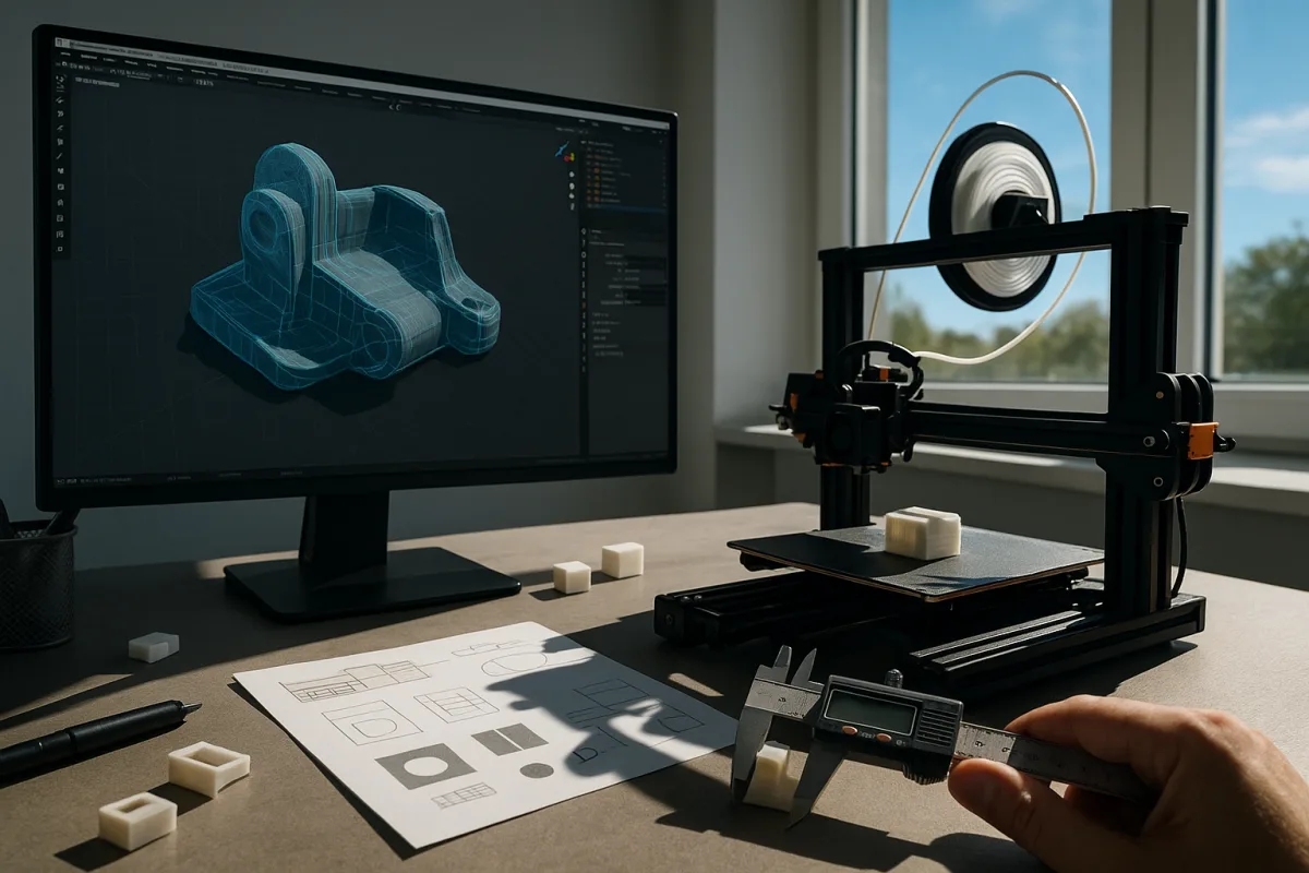
The useful mental model: a print needs one enclosed volume
The most useful Blender-for-printing tip is not really a button or modifier. It is learning to see your mesh as a closed container of material. A printer cannot manufacture a convincing silhouette. It needs a definite answer to one question: where does the solid begin and end?
That condition is usually called watertight or manifold. A watertight mesh encloses a volume with no gaps, no ambiguous edges, and no loose internal surfaces confusing the slicer. Every printable edge belongs to a coherent shell rather than terminating in empty space. [2]
This sounds basic, but it explains most of the frustrating failures people blame on export. A model may render perfectly in Blender because Cycles and Eevee only need visible faces. A slicer must convert those faces into physical layers, perimeters, infill, and support.
Think of a ceramic mug, not a game asset. The outside surface, inside surface, and rim together describe one continuous shell. Remove a tiny patch under the handle and the mug may still look fine on screen, but it no longer describes a dependable volume.
Why manifold geometry is stricter than good-looking geometry
A normal polygon mesh is often a skin. For rendering, it can overlap itself, contain hidden planes, or use one-sided faces without much consequence. Those choices may be messy, but lights and cameras can still produce a persuasive image.
A print mesh is closer to a manufacturing drawing. The slicer needs to identify an inside and an outside, calculate walls, and decide which regions receive material. Non-manifold edges, self-intersections, and internal duplicate faces make those calculations ambiguous. [1][5]
An open edge is the simplest failure. It has only one face attached when a closed shell needs a neighboring face to continue the boundary. A non-manifold edge can also have three or more faces attached, which is equally unclear physically.
Interior faces are less obvious. They commonly arrive after Boolean work, kitbashing, mirrored parts, or joining meshes that were never truly merged. The object looks closed from outside, yet an extra plane sits inside the supposed solid and can create unwanted slicer regions. [1]
Normals matter because they define which side of each face is outward. Blender can display a mesh that has some polygons flipped inward, particularly after importing scanned or AI-generated geometry. A slicer may interpret those reversals as holes, thin regions, or invalid shell boundaries. [5][8]
Start in a scale system that matches the object
I am describing this workflow in Blender 4.5 LTS. Before modeling or repair, set Scene Properties to Metric and use millimetres as the working display unit. For millimetre-scale work, set Unit Scale to 0.001. [10][14]
That figure has caused needless confusion because Blender’s default conceptual world is metres. With Unit Scale at 0.001, a displayed millimetre corresponds naturally to the size you intend to manufacture, rather than relying on an exporter or slicer to guess conversion.
Some published Blender printing guidance still recommends Metric with Unit Scale left at 1.0. [10] That can work in a controlled workflow, but it makes scale interpretation more fragile. The important point is not ideological loyalty to one setting, but consistent millimetres from model through slicer.
Confirm it with a small calibration object. Make a plainly measured block, export it, and check the dimensions reported by the target slicer. Different export settings and printer workflows can still introduce assumptions, so the printer’s result is the final authority. [14]
Apply object transforms before exporting STL, especially scale. In Blender, an object may visually measure correctly while carrying unapplied scale values from a previous resize. Applying transforms turns that object-level instruction into actual mesh dimensions, removing one common source of surprise. [5][7]
The inspection pass is where the model becomes printable
Blender’s 3D Print Toolbox is useful because it checks the geometry as a manufacturing shell rather than as an attractive asset. Enable the add-on in Blender 4.5 LTS, then use its analysis tools before trying to fix anything. [1][10]
Start by checking non-manifold geometry. Do not immediately run an automatic repair and assume the job is done. Selection results are information: zoom in and ask whether the marked area should be a seam, a deliberate opening, or a genuine closed connection.
Then inspect for intersecting faces, zero-area geometry, loose elements, and internal faces. A Boolean union between two objects may visually resemble a fused part while still retaining overlapping shells. Joining objects is not the same operation as creating one printable volume. [1][5]
For straightforward holes, select the boundary and fill it manually with F in Edit Mode. That is often preferable where the intended shape is clear, because you can see the new cap and decide whether its topology belongs with the surrounding form.
For more damaged imports, the toolbox’s Make Manifold operation can be a reasonable repair starting point. It is not magic. Automated repair may close intended openings, soften sharp details, or alter fragile areas, so inspect the result rather than trusting a green checkmark. [1][8]
Recalculate normals outward with Shift+N after repairing surfaces. This is a small operation with a large payoff because it restores a consistent inside-outside direction across connected geometry. Use face-orientation display as a visual check when the form contains complex cavities or imported data. [5][7]
Wall thickness turns a shell into a usable part
Watertight does not automatically mean strong. A mathematically closed shell can contain walls so thin that the printer cannot form them reliably. This is where the mesh stops being abstract topology and starts responding to nozzle diameter, exposure, resin behavior, and intended load.
For common FDM materials such as PLA and ABS, 0.8 mm is a widely cited minimum wall thickness. That is a starting floor, not a design target for a bracket, clip, handle, or threaded part expected to take force. [3][11]
Functional FDM parts generally call for 2 to 4 mm walls, according to the design guidance in PrintVX and Makelab’s material reference. [3][11] The exact choice depends on orientation, layer direction, geometry, material, and the printer’s own perimeter settings.
Resin printing can resolve finer surfaces, but it has its own brittleness and handling concerns. An SLA resin shell may begin around 0.8 mm, while functional parts commonly benefit from 2 to 3 mm thickness rather than chasing the thinnest possible result. [3][11]
Likewise, model detail must survive the process. Around 0.4 mm is a practical minimum feature size for FDM, while SLA can often reproduce features around 0.1 to 0.2 mm. [4][11] Those are process guidelines, not universal promises.
The reason is mechanical. An FDM nozzle lays down a bead with a finite width, so a tiny raised line may become one inconsistent extrusion or disappear entirely. Resin can resolve smaller forms, but unsupported fragile pins and embossed details still need physical strength.
Solidify is a thickness tool, not a repair tool
If your model began as a single surface, use Blender 4.5 LTS’s Solidify modifier to create actual walls. Enable Even Thickness and use Complex mode where the form has concave areas or intersecting details that simpler offset methods handle poorly. [10]
Solidify is especially useful for decorative shells, character busts, masks, and sculpted forms. It produces a consistent offset from the original surface, which is more dependable than manually extruding irregular surfaces and hoping every area ended with enough printable material.
For hollowing, set Solidify’s Offset to -1 so the added thickness goes inward and preserves the outer silhouette you modeled. This habit matters for fit-critical exteriors, although it is a habit rather than a rule for every design. [9]
A hollow FDM model commonly needs roughly 1.2 to 3 mm walls. Hollow resin pieces are often designed around 1.5 to 2.5 mm, balancing material use against the risk of cracking or deforming. [9][11]
Do not hollow first and inspect later. Ensure the original mesh is manifold before adding thickness, then inspect the resulting shell again. A flaw in the starting surface can become a more complicated flaw after offsetting, particularly around sharp recesses and narrow channels.
Drain holes make hollow forms physically honest
Hollowing resin models creates another version of the watertight problem. A sealed internal cavity can trap uncured resin and pressure. Drain holes give liquid a route out during cleaning and avoid leaving a hidden reservoir inside the finished object. [9]
Place drainage holes in inconspicuous, low-facing areas where possible, but do not let concealment defeat drainage. The hole has to reach the cavity and work in the print’s actual orientation. A beautifully hidden hole on the wrong side may accomplish nothing.
Guidance commonly suggests about 5 mm diameter drainage holes for resin prints. For FDM hollow pieces, 3 to 4 mm holes are a typical range. [9] Those dimensions depend on the specific object and process, so check the printer or service bureau requirements.
Reduce complexity only when it serves the print
Dense sculpt meshes are not automatically better print files. They can slow export, bog down slicers, and make repair harder, without adding any feature the printer can reproduce. The question is whether a polygon supports a visible, manufacturable change in the surface.
Blender’s Voxel Remesh can rebuild uneven sculpt topology into a more uniform mesh. Voxel size controls the retained scale of detail, while adaptivity can reduce unnecessary density in flatter regions. This is useful before repair when the original topology is chaotic. [12][13]
Decimate is a different tool. Collapse mode reduces general mesh density, while Planar mode is useful where broad flats should remain flats. Neither modifier knows what your printer can resolve, so compare the result against the smallest detail worth keeping. [10][13]
Do not read Decimate’s ratio as a guaranteed percentage reduction in every case. Its result can be unintuitive because Blender evaluates triangulated geometry, and quads or n-gons do not map cleanly to the face-count expectation users often bring to the control. [10]
Export the volume, not the Blender scene
Export only the selected print objects. Cameras, lights, reference meshes, hidden cutter objects, and decorative scene geometry have no place in the manufacturing file. This is basic housekeeping, but it prevents accidental exports that complicate diagnosis later. [5][7]
STL remains a standard print format, but it does not carry colour or richer manufacturing metadata. Use an STL tolerance around 0.1 mm as a practical export setting, then inspect the result in the slicer rather than assuming the export panel solved everything. [5]
Use 3MF when colour information or embedded slicer profiles matter to the workflow. Unlike STL, 3MF can retain more context about the intended print setup, although the receiving slicer and printer ecosystem must support the data you expect it to preserve. [6]
A realistic preparation budget is about 20 minutes for inspection, five for mesh repair, five for scaling and orientation, five for supports, and five for final checks. [8] That time is not bureaucracy. It is the cost of proving that a digital surface describes a printable object.
Frequently Asked Questions
How do I ensure my Blender model is watertight for 3D printing?
To make a model watertight, it must enclose a single continuous volume with no gaps, open edges, or internal faces. Use Blender’s 3D Print Toolbox add-on to identify non-manifold edges, holes, and interior faces. Recalculate normals to face outward (Shift+N), fill holes manually or with the toolbox’s “Make Manifold” feature, and remove duplicate geometry to ensure the mesh forms a sealed shell.
What are the best scale settings in Blender for 3D printing?
Set the Scene Properties to Metric units and choose millimetres as the display unit. Adjust the Unit Scale to 0.001 so that one Blender unit corresponds to one millimetre, ensuring accurate real-world sizing. Confirm scale accuracy by exporting a simple calibration object and measuring it in your slicer before printing.
How can I check and fix mesh errors in Blender before 3D printing?
Enable the 3D Print Toolbox add-on to detect common mesh issues such as non-manifold edges, holes, and inverted normals. Use its tools to highlight and repair these problems, or fix them manually by filling holes (with F), merging vertices, and recalculating normals. Inspect for interior faces that may confuse slicers, especially after Boolean operations or joining meshes.
Why is applying transforms important before exporting for 3D printing?
Applying transforms (Ctrl+A) ensures that scale, rotation, and location changes are baked into the mesh data. This prevents mismatches between Blender’s internal coordinates and the exported file, which can cause incorrect sizing or orientation in the slicer. It is a necessary step before exporting to formats like STL to maintain model integrity.
What wall thickness should I design for in Blender for 3D printing?
Wall thickness depends on the printing technology and material. For FDM printers using PLA or ABS, a minimum of 0.8 mm is common, but functional parts typically require 2 to 4 mm for strength. Resin prints also start at 0.8 mm minimum, with 2 to 3 mm recommended for durability. Always check your printer and material specifications for precise requirements.
How we researched this
This article was assembled from 14 cited references.
Nothing here is based on hands-on testing. Where a figure or finding appears, it belongs to the source cited beside it, and the writing says so rather than implying otherwise. Every source is listed below so you can check it.
Sources
- Mesh Repair | Blender for Visual Investigation
- Watertight 3D Models: Why They Matter for 3D Printing
- Minimum Wall Thickness for 3D Printing: Engineering Design Guide | PrintVX Blog
- Designing for 3D Printing: Tolerances, Wall Thickness, and Printability | PrintCalcs
- Preparing STL Files for 3D Printing — Complete Guide | Morphera
- Slicer Profiles — Blender 3MF Usage Guide — Clone-Core Docs
- How to Prepare an STL File for 3D Printing (2026) | Automatic3D
- printpal - Preparing AI-Generated Models for 3D Printing — Mesh Repair, Scaling, Orientation | printpal.io
- How to Hollow Out a 3D Model in Blender: Step-by-Step Guide
- The Complete Guide to Designing 3D Printable Models in Blender (2026 Edition)
- Wall thickness guidelines by material and technology | Makelab Help Center
- Remeshing - Blender 4.5 LTS Manual
- Remesh Modifier - Blender 5.1 Manual
- export - Scale settings for exporting to STL (for 3d printing) - Blender Stack Exchange
Related Articles
Blender Scale & Wall Thickness Setup for 3D Printing
Learn how to set scale and wall thickness in Blender to prepare accurate, printable 3D models for various 3D printing technologies.

Best Practices Exporting Models from Blender
Learn best practices exporting models from Blender, including applying transforms and choosing correct export settings for FBX and OBJ formats.
Blender Tips for Beginners: Master Object and Edit Modes
Learn essential Blender tips for beginners, including object vs edit mode, applying scale, and mastering transform shortcuts for better 3D modeling.
Blender Architectural Visualization Workflow
Learn the Blender architectural visualization workflow: import CAD, model accurately, set scale, and create realistic materials and lighting for renders.