
Blender Scale & Wall Thickness Setup for 3D Printing
Learn how to set scale and wall thickness in Blender to prepare accurate, printable 3D models for various 3D printing technologies.
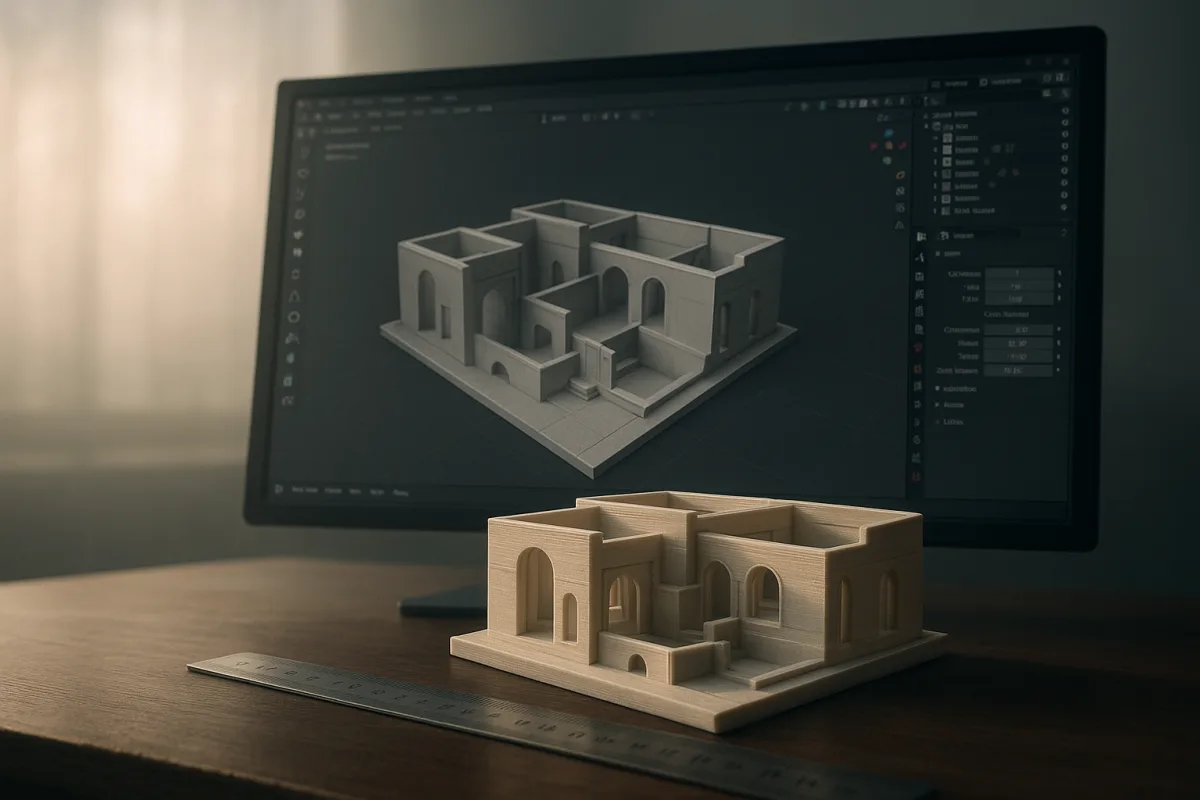
Start with the printer, not the mesh
The first preparation problem is usually not Blender topology. It is designing for an unknown manufacturing process. A model that looks completely reasonable for resin can be too thin, too fragile, or too support-heavy for an FDM machine.
Ask where the file will be printed before changing anything. At minimum, establish whether it is FDM, SLA or DLP resin, or SLS powder printing, and get the printer’s build volume from the operator or service bureau.
Those technologies impose different minimum wall expectations. General guidance places FDM around 0.8 to 1.2 mm, SLA around 0.5 to 0.8 mm, and SLS around 0.7 to 1.0 mm. [10][11][12][13]
Those numbers are starting constraints, not an artistic target. A thin decorative resin part and a load-bearing FDM bracket may need very different treatment despite technically meeting a minimum wall figure. Printer model, resin, filament, orientation, and intended use matter. [10][12][14]
This is where an all-purpose Blender asset often needs a rethink. A game prop may have floating panels, zero-thickness planes, separate bolts pushed into surfaces, and deliberately invisible intersections. A printable object needs physical continuity where those pieces must become one part.
If you sculpt in ZBrush, Nomad Sculpt, or Blender’s Sculpt Mode, the same manufacturing question applies. Bring the high-resolution shape into Blender 4.5 LTS if that is your preparation tool, but do not assume a watertight-looking sculpt is automatically a printable volume.
There is limited evidence for a detailed cross-application printing workflow beyond this common handoff. The useful principle is software-agnostic: inspect the final mesh in the application exporting it, at the actual physical scale, before it reaches the slicer.
Set real-world scale before measuring walls
Open the Blender 4.5 LTS scene properties and set Units to Metric, Length to Millimeters, and Unit Scale to 0.001. This convention makes one Blender unit equal one millimeter, which removes the familiar uncertainty of whether a value means metres, centimetres, or print-sized millimetres. [7][18]
Do this early, ideally before modeling. Retrofitting scale at the end is possible, but it makes every earlier visual judgement about bevel width, embossed lettering, sockets, and wall thickness less trustworthy.
Check the overall dimensions against the target printer’s build volume. Exceeding the build area is a common failure point, and a slicer cannot make an oversized one-piece object fit without scaling or cutting it. [17]
Use Blender’s Item panel to read dimensions, but inspect the proportions too. Uniformly scaling a finished model down can turn a previously safe 1 mm wall into an unprintable sliver, particularly around handles, ears, fins, or recessed cavities.
Once dimensions are right, apply scale with Ctrl-A, Scale in Blender 4.5 LTS. Unapplied object scale can confuse modifier behaviour and makes dimensions harder to reason about during preparation. Applying it establishes the object’s current dimensions as its actual mesh state. [1][17]
This is not merely tidy scene management. A Solidify modifier set to 1 mm should be evaluated against an object with predictable transforms, particularly if the model arrived from another package or was resized after import.
Turn a visual model into a closed volume
The next problem is manifoldness. In plain terms, the printer needs one or more volumes whose surfaces enclose printable space. A boundary edge, open hole, internal loose face, or non-manifold junction can leave the slicer unsure which side is solid. [3][15]
In Blender 4.5 LTS, enable the bundled 3D Print Toolbox from Edit, Preferences, Add-ons, then search for 3D Print Toolbox. The tool provides checks for common printability problems, including non-manifold geometry, intersecting faces, thin areas, and dimensions. [3]
Run a check before trying to repair everything manually. This is a good use of automation because it finds errors that are tedious to spot in a dense hard-surface mesh or a sculpt with thousands of irregular polygons.
Then inspect the reported areas in Edit Mode. Select Non-Manifold is one of the essential manual checks. It can reveal open boundaries, disconnected geometry, and topology configurations that do not describe a clean printable shell. [3][6]
A hole is not always obvious from the outside. Common sources include a deleted face under a boolean, an open underside left from a speed-modeling pass, or two mesh shells that appear joined but merely overlap.
Fix small openings by creating appropriate faces, then inspect the surrounding topology. For more consequential breaks, rebuild the local surface rather than filling an enormous irregular boundary with one cap and hoping the slicer interprets it well.
Intersecting objects need a decision. If they are meant to print as one fused piece, use a Boolean Union or otherwise merge them into a coherent solid, then recheck the result. If they are separate assembled parts, keep a deliberate physical gap.
Internal geometry is another frequent trap. Hidden duplicate surfaces and buried objects may not show in a beauty render, but they can create unpredictable slicer results. Remove geometry that has no role in the final manufactured form. [15][17]
Check normals before trusting the outside
Normals tell the slicer which way a surface faces. Flipped normals can make a watertight mesh behave as though portions are inside out, especially after mirrored modeling, booleans, or imported scans. [3][15]
In Blender 4.5 LTS, turn on the Face Orientation overlay. The viewport gives an immediate visual distinction between front- and back-facing polygons, making inverted patches much easier to isolate than they are under ordinary material shading. [3]
In Edit Mode, recalculate normals outward where the mesh is a conventional closed shell. Then turn Face Orientation back on and inspect again. Recalculation is useful, but it is not a substitute for looking at complex cavities, nested shells, or intentionally open surfaces.
Do not use a normal flip as a repair for non-manifold topology. It can alter the symptom without closing the hole or resolving an ambiguous intersection. First establish the volume, then ensure that volume has consistent outward-facing normals.
Give thin features enough material
Wall thickness is where rendering instincts can work against print preparation. A visually delicate flange, eyelid, blade, lettering stroke, or hollow vessel may look intentional at screen scale while being below the process’s reliable physical limit.
Use the 3D Print Toolbox thickness check in Blender 4.5 LTS as an initial scan, then compare its findings to the process specification. Its usefulness depends on you entering or interpreting a relevant threshold for FDM, SLA, or SLS. [3][10]
For FDM, beginning around 0.8 to 1.2 mm is typical guidance. That often means thin ornamental parts need to be thickened, simplified, or reoriented before export rather than left as a single near-zero-thickness skin. [10][12]
For SLA or DLP, the commonly cited 0.5 to 0.8 mm range permits finer forms, but it does not eliminate fragility. Long thin elements and hollow forms still need practical judgement about cleaning, handling, and the stresses created by supports. [10][12]
For SLS, guidance around 0.7 to 1.0 mm is common. SLS can support complex geometry with surrounding powder, but that does not mean every thin isolated feature is equally durable or every enclosed cavity is practical. [11][13]
If the model is hollow, ensure it is intentionally hollow. A Solidify modifier can establish a consistent shell, but inspect it closely around sharp corners and complex intersections, where self-intersections or uneven wall results can appear.
Hollow resin models also need a printer-specific plan for drainage and cleaning openings. The supplied guidance does not establish universal hole sizes, so get those requirements from the printer operator rather than copying a generic number into every model.
Deal with overhangs and separate parts now
A watertight mesh can still be difficult to print because gravity is part of the process. Unsupported overhangs, enclosed features, and narrow contact points may require supports or a different orientation. Ignoring this is a common preparation mistake. [17]
Blender can help you evaluate the shape, but the slicer is usually where support generation and orientation decisions become concrete. Export a test file early enough to see how the slicer proposes supports, islands, and layer direction.
Do not treat automatic supports as permission to ignore modeling. They can leave marks, add cleanup work, and fail to reach inaccessible areas. A change as simple as separating a component or widening a contact area can produce a more sensible print.
For assembled objects, model clearance intentionally rather than placing parts exactly face-to-face. Tolerance values vary materially by process, printer, material, and surface finish, so use the service provider’s recommendation instead of declaring a universal clearance value. [10][12][14]
Freeze the evaluated mesh before export
Apply modifiers once they represent the final printable form. This includes mirrors, booleans, subdivision, solidify, arrays, and any other operation that changes the physical mesh. A printer receives geometry, not Blender’s procedural intent. [1][17]
Inspect the result after applying, especially booleans and solidify. This is where a clean modifier stack can become a messy mesh with tiny slivers, open edges, self-intersections, or unexpected internal faces.
Triangulating is commonly recommended before export because triangles give the file a single, unambiguous surface representation. Blender 4.5 LTS can do this with a Triangulate modifier or the triangulate operation in Edit Mode. [15][16]
It is a habit worth understanding rather than a rule to perform blindly. Some slicers handle quads without trouble, so triangulation is not universally necessary, but it can make the exported mesh more predictable when downstream software is uncertain. [15]
If triangulation noticeably changes the shading, remember that print preparation is concerned with geometry, not viewport smoothness. Check the actual faceting and silhouette, particularly on curved sculpted objects where polygon density may be too low for the intended physical finish.
Choose STL or 3MF, then verify in the slicer
STL remains the safest compatibility choice because it is widely supported across slicers and print services. It describes the mesh surface but carries relatively little contextual information beyond geometry. [9][19]
3MF is increasingly useful where the slicer and print service support it. It can retain richer manufacturing-related data than STL, making it a better option when the receiving workflow is built around 3MF rather than treating it as an afterthought. [9][19]
OBJ and STEP have legitimate roles elsewhere in 3D work, but they are generally less suitable choices for this final print-preparation handoff. STEP is associated with CAD-style solid exchange, while OBJ is not the primary print-delivery format here. [9][19]
In Blender 4.5 LTS, export only the intended objects. Verify that export scale is correct, then open the resulting STL or 3MF in the actual slicer. This second import is where you catch a surprising number of scale, orientation, and missing-geometry mistakes.
Use slicer repair tools as a final safety net, not as the main modeling strategy. Simple models may be checked, repaired, and exported in minutes, while complex sculpts, assemblies, or hollow parts need longer manual inspection. [3][17]
The final question is not whether Blender reports zero errors. It is whether the slicer sees the dimensions, shells, wall thicknesses, orientation, and support problem you intended. That printer-specific review is the last useful checkpoint before material, time, and post-processing become involved.
Frequently Asked Questions
How do I set accurate scale in Blender for 3D printing?
Set Blender 4.5 LTS to Metric units, Length to Millimeters, and Unit Scale to 0.001. This setup makes one Blender unit equal to one millimeter, ensuring that all measurements correspond directly to real-world sizes. It is best to do this early in the modeling process to maintain accurate proportions and wall thicknesses.
What wall thickness should I use in Blender for different 3D printers?
Recommended minimum wall thickness varies by printing technology: about 0.8 to 1.2 mm for FDM, 0.5 to 0.8 mm for SLA resin, and 0.7 to 1.0 mm for SLS powder printing. These are starting points and must be adjusted based on the specific printer model, material, orientation, and intended use of the part.
How can I ensure my Blender model is a closed volume for 3D printing?
Make sure the model is a closed, consistently oriented solid before exporting. This means no holes or gaps in the mesh and all normals facing outward. Use Blender’s Select Non-Manifold tool and Face Orientation overlay to identify and fix issues like holes or flipped normals.
Why is applying scale important before exporting for 3D printing?
Applying scale ensures that the model’s dimensions in Blender match the intended real-world size. Without applying scale transforms, measurements like wall thickness and overall size can be incorrect when exported, leading to failed prints or parts that do not fit the build volume.
How do I check and fix mesh issues in Blender before 3D printing?
Use Blender’s 3D Print Toolbox to identify common problems such as non-manifold edges, holes, and flipped normals. Manually inspect the mesh with the Select Non-Manifold tool and Face Orientation overlay to find and correct errors. Remember that these tools aid inspection but do not guarantee print success, so manual review and printer-specific adjustments remain necessary.
How we researched this
This article was assembled from 20 cited references.
Nothing here is based on hands-on testing. Where a figure or finding appears, it belongs to the source cited beside it, and the writing says so rather than implying otherwise. Every source is listed below so you can check it.
Sources
- How to Use Blender for 3D Printing: Step-by-Step Guide | Leyaa.ai
- Can Blender be used for 3D printing? - Rapid Prototyping Solutions
- Prepare Blender Models for 3D Printing: 3D Print Toolbox Guide
- Can You Print 3D Models from Blender? A Simple Guide
- Blender Tutorial: 3D Modeling in Blender for Beginners
- Creating 3D models for printing with Blender: Advanced tips | Opensource.com
- Blender Quick Tip: Set Up Units for 3D Printing | Simmer3D
- How to 3D print from Blender (the one-click workflow) - SimplyPrint
- 3D printing file formats: STL, 3MF, STEP and OBJ explained | 3D Printing Dublin
- Designing for 3D Printing: Tolerances, Wall Thickness, and Printability | PrintCalcs
- Wall thickness 3D print: guidelines for strong, reliable parts - Sinterit – Professional SLS 3D Printers & Accessories
- 3D Printing Tolerances & Design Rules: FDM vs SLA vs DLP | EOD Cube | EOD Cube
- 3D printing tolerances and wall thickness — table | FormHub
- Additive Manufacturing Tolerances & Capabilities | Mech Codex
- Preparing STL Files for 3D Printing — Complete Guide | Morphera
- From Blender to 3D printing: a workflow for static models
- 🚀 How to Prepare a 3D Model File for Printing: 12 Critical Steps (2026) - 3D Printed
- Set Up Millimeter Units in Blender for 3D Printing - blender
- 3D Printing File Formats: STL, 3MF, OBJ, and More Explained | FabRapid 3D
- STL Converter: Preparing 2D Images for 3D Printing (2026) | Geomeris
Related Articles
Blender 3D Printing Tips
Learn essential Blender 3D printing tips to prepare watertight, scaled, and repair-checked models for reliable 3D printing results.
Blender Project Setup for Animation: Best Practices
Learn how to set up a Blender project for animation with proper folder structure, naming, frame rate, and collaboration tips.

Best Practices Exporting Models from Blender
Learn best practices exporting models from Blender, including applying transforms and choosing correct export settings for FBX and OBJ formats.
Using Blender for Education
Learn how to use Blender for education with tips on setup, hardware, and teaching modeling, lighting, and rendering effectively.